Steam Traps for Tracing Applications
Steam tracing is used across various industries to heat trace the product or raw material line at a specific temperature so as to maintain their fluid state and enable pumping and distribution. Heat tracing maintains viscosity and prevents crystallization or solidification.
Steam tracers can be implemented in two ways: as a network of smaller pipelines running parallel to the process lines or as jackets surrounding the process lines, pipeline accessories and pumps. Tracing systems are often intricate, with multiple tracers for each process line.
Maintaining a uniform temperature of product / raw material across the entire length of the tracing network is crucial.
Typical issues observed across tracing lines include :
- Unplanned shutdowns due to choking of product lines.
- Corrosion and leakage of tracer lines and tracer jackets.
- Need to keep steam traps bypassed to attain uniform heating.
- Recurring failure of product transfer pumps as the required product pumping viscosity is not attained.
- Higher steam consumption
- Tracing condensate is drained.
Most of these issues can be attributed to incorrect design of the tracing network, poor steam trap uptime, incorrect steam trap selection or missing traps on tracers.
Selection
As steam flows through the tracer lines / jackets, it transfers its latent heat to the process pipeline, maintaining the temperature of the process fluid, and condensing back into water. The temperature to be maintained depends on the type of product / raw material being traced and in many instances, besides using the latent heat of steam, it is also possible to use some portion of the sensible heat for tracing without impacting tracing efficacy. Utilising sensible heat lowers the overall steam required in tracing. Thus thermostatic traps are best suited to effectively evacuate condensate from tracing networks. These traps incorporate a thermostatic capsule that holds back the condensate and allows it to be discharged only when it cools down to a specific temperature. This mechanism ensures that some amount of sensible heat is used within the tracing network.
Thermostatic traps are available with capsule choices that operate at 6, 12 or 24oC below steam saturation temperature. Depending on the AT (temperature difference between steam and product), these options allow a plant to utilise the maximum sensible heat. It is recommended to select the capsule in a way that ensures the AT does not fall below 35C.

However, in case of some specific products / raw materials where minor deviations in product temperature cannot be tolerated, it is not recommended to hold back condensate until it sub cools. In such critical tracing applications thermodynamic steam traps are the best choice. For example while tracing gases which contain sulphur minor deviations which bring the temperature down to the sulphur dew point can cause corrosion thereby detrimental to the piping.
Sizing and Installation
Sizing
The condensate load in an individual tracer line is miniscule as steam is only required to compensate for the heat loss in the insulated product line due to radiation and hence sizing considerations are not significant.
Installation
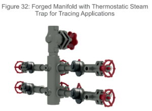
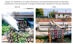
Conventionally designed tracing networks can be a complex maze of piping that not only occupy a large footprint but are also difficult to operate and maintain efficiently. Distributing and controlling steam and recovering condensate from the tracing network is a challenge primarily due to incorrect design and installation issues. Poor design and installation issues of steam tracer systems also results in higher maintenance costs, including reduced life of the tracing system and poor steam trap uptime. The average uptime observed is as low as 35% for steam tracing traps. A properly designed network encompassing forged steam and condensate manifolds can simplify the piping network. While steam manifolds can enable centralized distribution of steam to multiple tracers, condensate manifolds can serve as central collection points for condensate from multiple tracers. These manifolds incorporate valves, allowing for isolation of steam or condensate from each individual jacket or tracer line. Condensate manifolds additionally also incorporate the steam trap.
The illustration below demonstrates the significant impact that correct design can have on operational efficiency and maintenance of the steam tracing system.

Install a separate steam trap for each individual tracer line / jacket
A common practice across plants is to use a single trap to cater to the condensate evacuation from multiple tracers or jackets. This practice of group trapping often results in problems of attaining desired temperatures and non-uniform (uneven temperatures) across the length of the tracing network, Group trapping of two or more tracer lines should be avoided even when these multiple tracers are tracing the same segment of the product line.
Install a separate steam trap for every tapping taken from the main tracer
In addition to the pipeline itself, pipeline accessories like valves also need to be traced to avoid temperature drops and solidification / congealing within them. An individual steam trap should be provided for every such tapping taken from the tracer
Changes in elevation should be avoided while routing the tracer around a flange
When the tracer line extends across the process pipeline flange, it is recommended to route the tracer horizontally across the flange. Vertical routing can lead to condensate accumulation and its associated problems.
Tracer lines should be provided with a slope in the direction of steam flow
