Steam traps for process applications
Steam is a widely used heating medium in diverse processes across a wide range of industries including textiles, pharmaceuticals, chemicals, paper, food and beverages. As steam transfers its latent heat to the process, it condenses back into water. This condensate needs to be evacuated from the heat transfer area as soon as it is formed as it impedes heat transfer efficiency. If condensate is allowed to accumulate within the steam space of equipment or heat exchangers it can hinder the attainment of desired process temperatures, cause
delays in achieving temperatures within specified time frames and result in uneven heating. These problems can ultimately have a detrimental impact on production, manifesting either as poor product quality (higher rejections or reworks) or reduced productivity (extended process times due to higher time taken to reach desired temperatures).
Selecting and installing the right steam trap prevents condensate accumulation in the process equipment, ensuring operation at optimal performance levels and safeguarding product quality and productivity without compromising on energy efficiency.
Selection of steam traps for process applications
Ideally, for process applications, the following considerations need to be kept in mind while selecting the steam trap.
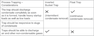
Ball float steam traps are the best choice due to their continuous discharge characteristics. Traps with intermittent discharge characteristics, e.g. Inverted Bucket/Thermodynamic type, lead to condensate logging in the equipment and consequently impact the process as well as energy consumption. The steam loss through and from the steam trap as per the International Standard ISO7841 (1988) and European Standard CEN27841 (1991) for Inverted Bucket vs Float traps is indicated below.

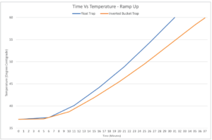
The table above indicates the energy requirements expressed in kilograms/hour of steam for 1/2 inch traps at a pressure of 5barg. As seen in the table above, when we compare a float trap versus an inverted bucket trap under no load conditions, the steam loss due to radiation from the inverted bucket trap is significantly higher. Plant after plant, our own observations across industries indicate significant gains in process and energy efficiency after replacing inverted bucket steam traps with float traps. For example, at a tyre plant we found that steam consumption per batch on the tyre press reduced from 17.91kg/hour to 14.80 kg/hour. Similarly, when a float trap was installed instead of an inverted bucket trap on a batch reactor in a plant, the desired process temperature of 60C was attained faster (31 minutes compared to 37 minutes) while also reducing steam consumption (118.5kgs versus 161.5kgs). The chart below highlights the Time Temperature Profile
Ramp up comparison plotted for both traps on the batch reactor.
Two orifice float traps
Traditionally, float traps have typically featured a single orifice for condensate discharge. However, in many processes, particularly in batch operations, steam demand during start up is significantly higher than the running load. Often, startup demand can be two to three times higher than the running load. Conventional steam traps are not able to evacuate heavy startup condensate loads effectively, leading to condensate logging in the equipment steam space.
As can be seen in the illustration below,
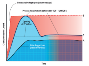
A. If the process trap is not selected and sized correctly, the heat exchanger gets waterlogged during start up, leading to lower heat transfer to the process.
B. When the bypass valve is opened to overcome this problem, it removes condensate but at the same time also leads to steam loss.
C. Float traps which have two orifices are specifically designed to handle both startup and running condensate loads. When the condensate load is low (running load) the float rises to open just one orifice, however at startup when the condensate load is much higher, the float rises further, opening both orifices.
This feature ensures that process temperatures are achieved within the required time frame, eliminating the need to bypass the steam trap. As a result production goals can be met without compromising on energy efficiency.
Avoiding stalling in temperature controlled applications
Most equipment heat exchangers are designed to cater to the maximum expected process heat load. However, in reality the heat load varies significantly based on operating conditions. As soon as the process temperature is attained, the temperature control valve installed on the equipment throttles reducing the steam supplied to the equipment. This reduces the pressure within the heat exchanger.
Steam traps discharge condensate based on the differential pressure across them. In order for the trap to remove condensate effectively, sufficient differential pressure should be present across it Le. the trap inlet pressure P1 should be much higher than the trap outlet pressure P2 (see illustration).
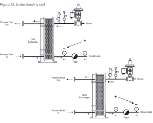
However, when the pressure in the heat exchanger P1 is equal to, or less than, the total backpressure acting on the outlet of the steam trap P2, the trap is unable to discharge condensate (see illustration). This inability to evacuate condensate effectively from the heat exchanging equipment is termed as “Stall’, Flooding of condensate in the process equipment reduces the effective area available for heat exchange impacting product quality due to uneven / poor heat transfer. It can also result in other issues like fouling, corrosion, ruptures within the heat exchanger and increased energy consumption.
A good indicator of stalling is if the temperature of the steam trap is noticeably cooler due to sub-cooling of condensate. Frequent cycling of the control valve between its open and close position can also be indicative of stalling in the heat exchanger. During regular operations, personnel frequently bypass the steam trap to quickly evacuate condensate as soon as they face difficulties in attaining process temperatures. However, this results in both steam loss and localised condensate drainage, a practice that is both unsafe and inefficient in terms of energy usage.
For example, the required hot water temperature in a bottle washer at a food and beverage plant is 85 degrees centigrade. During startup the inlet water temperature to the heat exchanger is at 30 degrees and subsequently the temperature rises. In the running condition the inlet water temperature increases to 80 degrees. The back pressure on the trap is 0.5barg and at peak load the supply steam pressure is
0.7barg. Considering these operating parameters, it is easy to compute the stall load and the temperature of hot water at the point when the heat exchanger stalls. The stall load can be computed using the following formula : % Stall loud = D-B / A-B
Where,
A = The steam temperature in the steam space at full load (Degrees Centigrade)
B = The secondary fluid outlet temperature (Degrees Centigrade)
D = Saturated steam temperature (Degrees Centigrade) equivalent to the back
pressure.
The stall load can also be computed using SteamHub, a mobile application, available on the play store / app store. The output of the application is illustrated below.
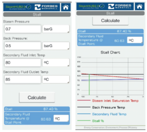
In case of the bottle washer, the current stall load is 87% and the secondary fluid temperature at stall point is 80.6 degrees centigrade.
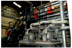
Here, we observed that the operators were bypassing the steam traps to evacuate condensate and minimise the adverse effects of stalling. The steam loss through the 25NB bypass kept 50% open was found to be 1,560kllograms/day (468,000 kilograms/year). Replacing the ball float steam trap with a Steam Operated Pump Trap not only eliminated this steam loss but also led to an improvement in the bottlewasher startup time and heat exchanger uptime, operation at rated speeds and consistent temperatures in each soak.
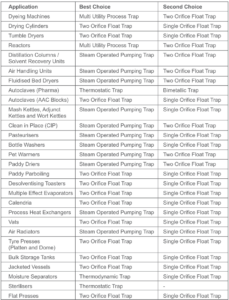
The table below lists the best suited process trap for different process equipment.
Installation considerations for float type steam traps
5.2.1 Orientation of the trap:
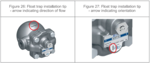
Float type steam traps should always be installed with the float arm in a horizontal plane so that the float arm rises and falls vertically. Typically, a directional arrow present on the trap indicates this. A float trap installed upside down will either fail open or closed whereas a float trap installed backwards will leak steam.
The trap should always be installed in line with the directional arrows indicated by the
manufacturer (see illustration below).
Good engineering practices to adhere to while installing process steam traps
Steam traps should always be installed at a practical working height
All steam traps need to be periodically inspected and maintained and hence it is advisable to install them at a practical working height, preferably close to the ground. This placement greatly simplifies the process of inspection, maintenance and repair.
Traps that are difficult to access are often overlooked and become a significant source of steam loss.
Steam traps should always be provided with a bypass valve and an upstream and downstream isolation valve
As a standard maintenance practice, it is recommended to clean the internals and strainers of steam traps every quarter. It is important to have a bypass valve and an upstream and downstream isolation valve in place so that it is possible to safely attend to the steam trap.
High pressure and low pressure steam traps should not be connected to the same condensate collection header
In practical situations, equipment using different steam pressures are placed alongside each other. To simplify the implementation of condensate recovery piping, it is a common practice to connect all of these steam traps to the same common condensate return line. However, the steam pressures used across these equipment varies. When traps of different process equipment which use both high and low pressure steam are connected to the same condensate collection header, the downstream pressure increases. As a result the differential pressure across the steam trap of the equipment using low pressure steam decreases. This reduces the discharge capacity of the low pressure traps, resulting in condensate accumulation in the equipment. This not only hampers heat transfer but also poses a risk of equipment damage and leaks due to water hammer.
Individual trapping lowers process time and reduces steam consumption
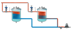
A common practice across plants is to use a single trap to cater to condensate evacuation from more than one equipment or more than one heating element of the same equipment. This practice is typically prevalent across equipment like dryers (where multiple coils are group trapped), vertical drying ranges (where multiple cylinders are group trapped), storage tanks (where multiple heating coils are group trapped) and platen presses (where multiple platen are group trapped). When two equipment are group trapped (see illustration below), if one equipment has almost reached the desired temperature (left) it will condense less steam as compared to the other equipment (right), that has just begun to attain the temperature. As steam from the first equipment reaches the trap it would remain closed hampering condensate evacuation from the other equipment. Common problems faced across such equipment include poor productivity, not being able to attain process temperatures or process parameters, high startup times, coil failures and steam leakage due to water hammering and higher energy consumption.
Avoid returning condensate by steam trap pressure
Recovering condensate by trap pressure is a common practice across many plants. The steam outlet after the trap is directly connected to the boiler feed water tank (see image below of a typical arrangement of condensate recovery by trap pressure from a process equipment). The line after the steam trap is lifted vertically and connected to a common collection header and given the pressure in steam, it is expected that condensate will travel the distance from the equipment to the feed water tank without a pump.
Although, recovering condensate this way may seem fairly simple from an implementation perspective, this design actually introduces various disadvantages that directly impact key performance indicators of the plant. The condensate discharge capacity of a steam trap depends on the trap type, trap size and the differential pressure across the trap. When the steam trap is used to return condensate to the feed water tank, it introduces a backpressure on the trap. The backpressure is due to the distance the condensate has to travel, the presence of bends and elevations in the pipeline, and the connection of steam traps with different pressures in the same pipeline.
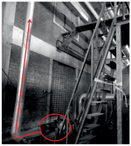
As the backpressure increases, the differential pressure across the trap reduces. As a result, the condensate discharge capacity of the trap reduces, leading to insufficient condensate evacuation from the process equipment and diminished heat exchange.
Disc Check Valves (Non Return Valves) should always be installed after the steam trap especially when the steam trap is discharging in a common condensate return line
A disc check valve allows flow in only one direction. By installing a disc check valve downstream of the trap, it prevents backflow (reverse flow) of condensate into the equipment, thereby avoiding flooding of the steam space. Additionally, the check valve also serves to protect the steam trap from adverse effects of backflow including mitigating potential damage due to hydraulic shock in the condensate line. This helps prolong the life and performance of the steam trap and the process equipment.
Steam traps should always be installed as close to the process equipment condensate outlet as possible
The pipeline from the equipment outlet up to the steam trap should be kept as short as possible. One may believe that as long as there is a steam trap, locating it a few meters away from the process equipment outlet would not matter. However something as trivial as this can prevent the steam trap from functioning properly. Steam traps are designed to trap steam and discharge condensate. When the steam trap is located at a greater distance from the equipment, the trap can get steam locked i.e. steam can flow over the condensate and collect in the line, blocking the flow of condensate to the trap. In such a situation, the steam trap will remain closed and not discharge condensate.
Condensate will only reach the trap and be evacuated once the steam that is blocking it condenses. Up to this point, condensate formed in the process equipment will continue to back up in the line and process equipment. This will hamper heat transfer and affect the process.
Select steam traps with a built-in steam lock release to prevent steam locking of the trap
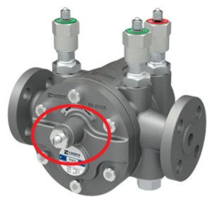
While steam traps should always be installed in close proximity to the process equipment, situations may arise due to site constraints
when this is not possible. In such cases it is recommended to select and install a steam trap with a built-in steam lock release (SLR) feature. The SLR unit is a manual needle valve which is designed to pass a small amount of steam. By facilitating the removal of steam this mechanism prevents steam locking, thereby enabling the trap to function properly. The SLR should however not be kept in the fully open condition, as this leads to steam loss and can also result in premature trap failure or the need for frequent maintenance.
Steam traps should always be installed below the equipment being drained
To ensure that condensate flows by gravity to the steam trap, it should always be located below the equipment being drained. For equipment drain lines it is recommended that the pipeline from the equipment outlet falls vertically for at least about 10 pipe diameters to the steam trap. This ensures that condensate does not accumulate at the bottom of the equipment, preventing corrosion and damage due to water hammer.
Vertical lift of the discharge line after the steam trap should be avoided
When the discharge line after the trap is vertically lifted, it introduces back pressure on the steam trap which can interfere with the proper operation of the steam trap and reduce its capacity to discharge condensate. It is ideally recommended to have a vertical drop in the condensate line immediately after the equipment outlet and a gradual slope in subsequent lines to facilitate flow of condensate to the condensate pump by gravity.
Sizing of process steam traps
Steam is used as a heating medium across diverse process applications. Selecting the right steam trap can lead to improved energy efficiency, reduced maintenance costs, and enhanced overall system performance.
Most plants size steam traps based solely on the equipment’s condensate outlet pipeline size. However, the steam trap’s ability to handle the equipment’s condensate load i.e. it’s condensate discharge capacity does not have any correlation with the end connection size. Sizing the steam trap based on this premise can result in an oversized or undersized steam trap.
In order to do choose the right steam trap, the following key aspects need to be considered:
| Facts to consider | Impact |
|---|---|
| Equipment peak and minimum steam load | Ensures that the steam trap can handle the condensate load and is neither over or undersized |
| Steam pressure to the equipment | Ensures that the steam pressure is less than the maximum allowable pressure of the trap |
| Minimum and maximum operating temperature | Ensures that the operating temperature is less than the maximum allowable temperature of the trap |
| Presence of temperature control | Temperature controlled processes requiring <100C are likely to face stalling |
| Back pressure (consider system back pressure including lift after the trap, frictional losses, etc) | Select the right differential pressure to ensure that the trap can overcome the backpressure |
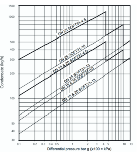
To select the right size, refer to the manufacturers capacity chart. For example, lo correctly size a single orifice float trap, one would require two key parameters i.e. the differential pressure and the condensate load. When the condensate load is 500kilograms/hour, the supply steam pressure is 3barg and the back pressure is 1barg (the differential pressure is 2barg), a DN25 SOFT31-4.5 is suitable to cater to the load. The trap size is selected by looking at the point where the load and differential pressure intersects and evaluating which steam trap size best meets both conditions.
