Steam Traps For Mainline Applications
One of the main objectives of a good steam distribution system is to deliver dry steam to the process. However, due to heat loss to the ambient surroundings, steam condenses along the entire length of the distribution network. This condensate needs to be evacuated as soon as it is formed as accumulation of condensate within the steam lines can lead to water hammer or wet steam formation.
While water hammer can cause severe damage to pipelines and accessories and compromise plant safety, wet steam with its lower latent heat can impede heat transfer efficiency and impact the process output (poor productivity or product quality). Steam traps ensure that condensate formed within the pipelines is evacuated preventing water hammer or wet steam.
Steam Trap Selection
Thermodynamic steam traps are considered to be the best choice for evacuation of condensate from the steam distribution pipelines.
Thermodynamic steam traps have several advantages over mechanical and thermostatic steam traps. For example, the OPEX for Thermodynamic steam traps is significantly lower vis-a-vis Inverted Bucket steam traps installed on mainlines as illustrated in the table below.
The steam loss through and from the steam trap as per the International Standard ISO7841 (1988) and European Standard CEN27841 (1991) is indicated below:
Table: Steam loss through and from steam traps
| Trap Type | Steam Loss Through Trap | Steam Loss From Trap | Total Steam Loss |
|---|---|---|---|
| Inverted Bucket Trap | 0.5 | 1.2 | 1.7 |
| Thermodynamic Steam Trap | 0.5 | 0.25 | 0.75 |
Our own experience across thousands of plants indicates that there is a significant benefit in terms of opex by installing thermodynamic steam traps instead of inverted bucket steam traps.
The data in the table below from a process plant highlights the impact of using thermodynamic steam traps versus inverted bucket steam traps on main lines.
Table: Impact of thermodynamic vs inverted bucket steam trap on main lines
| Parameters | Inverted Bucket Trap | Thermodynamic Trap |
|---|---|---|
| Condensate quantity collected (Kilograms) | 7.77 | 6.68 |
| Final water temperature (°C) | 53.3 | 50.4 |
| Steam pressure on the header (Barg) | 10 | 10 |
| Trial duration (minutes) | 70 | 70 |
The higher temperature by 3°C and the higher condensate load by 0.934 kilograms/hour in case of the inverted bucket trap is on account of the higher steam loss through and from the trap. Annually this amounts to 7,845 kilograms (7.8Tons) of steam loss from a single trap. Given that most plants have upwards of 50 mainline steam traps this loss can amount to about 392,280 kilograms of steam annually.
Thermodynamic steam traps also have several other advantages. They are suitable for both high and low pressure systems. They are highly resistant to damage due to water hammer, which is important, considering that even in a well-designed network, water hammer can sometimes occur. In some areas prone to sub-zero temperatures, freezing can also cause problems, particularly for lines exposed to the environment.
In such cases too thermodynamic steam traps are recommended since they are resistant to freezing. Thermodynamic steam traps are very easy to maintain, offering a long service life.
A mainline steam trapping station should have an inlet isolation and outlet isolation valve, a strainer, a trap bypass valve, a trap depressurisation valve and a trap test valve. In a conventional steam trapping station, all of these individual accessories
are connected together with piping to build the station making it not only cumbersome to install but also difficult to maintain.
Read more: Conventional Steam Pipeline Trapping Station vs. Advanced Mainline Steam Trapping Solution
Steam Trap Sizing
Given that steam distribution pipelines are almost often insulated, the quantum of condensate that will be formed is very little. Thermodynamic steam traps that are
installed on the steam pipelines should be sized such that they have sufficient capacity to evacuate the quantity of condensate formed.
The table below indicates the quantity of condensate formed under working conditions (warm-up and running loads) for different pipeline sizes.

The illustration below represents the discharge capacity of a Compact Module Thermodynamic Trap.
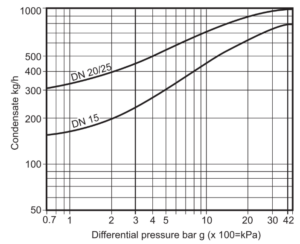
As can be seen from the capacity chart a 15NB thermodynamic steam trap installed at 30 meter intervals has sufficient capacity and is hence is more than adequate to evacuate condensate formed within the pipelines.
Installation considerations for mainline steam traps
4.3.1 Orientation of the trap
Thermodynamic steam traps should be preferably fitted in a horizontal pipe with the cap on the top. While the trap can work in other positions also, it will reduce its
service life. The trap should also always be installed keeping in mind that the direction of flow is in line with the direction of the arrow indicated on the trap body (see illustration below). A thermodynamic steam trap installed backwards will leak steam.

4.3.2 Locations where mainline steam traps should be installed:
For saturated steam distribution lines steam traps should be installed at the following locations:
At every 30 meters: Installing steam traps every 30 meters ensures that condensate is removed at regular intervals, preventing its accumulation.
At every change in elevation: Condensate typically accumulates at low lying points within the distribution network. Absence of a drain pocket and steam trap at such locations will result in water hammer which damages the pipeline and leads to steam leaks.
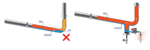
At dead ends: Due to the slope provided in the steam line, condensate will accumulate at dead ends within the steam pipelines. If drain pockets and steam traps are not present at these dead ends it will lead to frequent failures of the flange gaskets due to water hammer as well as result in supply of wet steam to the process.
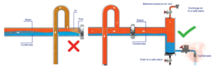
On headers: Typically steam headers are designed for steam velocities of 15 meters/second. This reduced velocity ensures effective separation of steam, air and
condensate and thus headers should be provided with steam traps to evacuate condensate. Yet many plants do not provide steam traps at headers (see image below). This has a direct impact on the steam quality supplied to the process (wet steam) which impedes / reduces heat transfer efficiency.
Before a process equipment: Regardless of whether it’s a batch-type or continuous process, at some point, steam to the process equipment will be shut-off, either due to the process requirement or during a shutdown. When steam is not needed and the steam inlet valve (manual valve / control valve) is shut, condensate that is formed in the line will continue to accumulate before the valve. If this condensate isn’t removed, it will flow into the equipment when the inlet valve is opened again, potentially causing damage to the pipeline, associated components, and the process equipment itself. Thus it is advisable to provide a steam trap before a manual/control valve installed on the steam supply line to a process equipment.
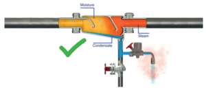
Along with moisture separators: While strategically located drain pockets and steam traps will remove condensate formed in the steam pipelines, they will not
remove water droplets suspended in the steam. To remove these suspended water droplets, moisture separators are installed in the steam pipelines. Steam traps
should be installed along with moisture separators to evacuate this entrained moisture that gets separated from steam.
4.3.3 Good engineering practices to adhere to while installing mainline steam traps
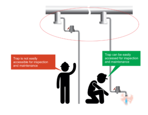
Steam traps should always be installed at a practical working height
Given that mainline steam traps are installed at 30-meter intervals throughout the extensive distribution network, a typical plant may have a substantial number of steam traps, potentially numbering in hundreds. As steam traps need to be periodically inspected and maintained, it is advisable to install these traps at a practical working height, preferably close to the ground. This placement greatly simplifies the process of inspection, maintenance and repair. Traps that are difficult to access are often overlooked and become a significant source of steam loss.
Mainline steam traps should always be provided with a bypass valve and an upstream and downstream isolation valve
As a standard maintenance practice, it is recommended to clean the internals and strainers of thermodynamic steam traps every quarter. In addition to such routine maintenance, there may also be situations where immediate attention is required, such as when a steam trap is leaking or blocked. Given that steam lines remain charged year round, except during a plant shutdown, it is impossible to safely attend to the steam traps unless isolation and bypass valves have been provided and are not themselves leaking. Our observations indicate numerous such instances where maintenance / rectification cannot be carried out as the trap cannot be safely isolated either due to the absence of a valve or due to a jammed / leaking valve.
Thermodynamic steam traps should be installed with an adequately sized drain pocket to capture condensate formed in the pipelines
Steam flowing in the pipelines at a speed of about 25 meters/second (90 kilometers/hour) will carry condensate present in the pipelines at similar speeds. Although a 20 millimeter drain pipeline has sufficient flow capacity, it is unable to capture much of the condensate which is moving at high speed. This leads to condensate accumulation within the lines despite installing steam traps, as condensate does not reach the trap.
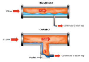
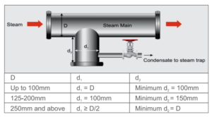
Condensate accumulation within the pipelines leads to waler hammer or wet steam. Correctly sized drain pockets should be provided to capture condensate formed in the lines so that it can roach the steam trap and be effectively evacuated. Use the guidelines below to size the drain pocket.
The inlet line to the steam trap should always be taken from the side of the drain pocket and not the bottom
Debris can occur in steam systems due to number of reasons e.g. rust due to corrosion of the metal surfaces like pipes and valves, scale due to poor water quality or carryover from the boiler and foreign debris introduced to the system during maintenance and repair like welding slag, dirt, etc. When the steam trap tapping is taken from the bottom of the drain pocket, any debris present in the lines can flow directly into the trap, choking it and damaging its internal components.
It is always recommended to take the tapping to the steam trap from the side of the drain pocket. Furthermore, this tapping should be situated at a height from the base, creating a dirt pocket that allows settled dirt or debris to accumulate without obstructing the trap’s inlet. A flush valve installed on the drain pocket facilitates flushing of the line to remove the dirt and debris that settles at the bottom.

