Steam Pipeline Sizing
Steam pipe sizing can be done based on two methods, i.e. the velocity method and the pressure drop method.
3.3.1 Velocity Method
While sizing the steam lines using the velocity method, the steam velocity is assumed and the line size is calculated for the required steam flow-rates by the following formula :
| Q | = A x v |
|---|---|
| Where, Q | = Volumetric flowrate (m3/s) |
| = (Steam Flow in Kg/hr x Specific Volume M3/kg) / 3600 | |
| A | = cross-sectional area of a pipe formula (m2) πD2/4 |
| V | = steam velocity (m/s) |
Since Q and v are known values in the above equation, A and hence D can be calculated.
The velocities assumed for calculating the line size for the following are:
| Flash Steam | = 15m/s |
|---|---|
| Saturated Steam | = 25m/s for long distance travel (>30 meters) |
| Saturated Steam | = 30m/s for short distance travel (<30 meters) |
The steam velocity should not exceed the above values as it can cause heavy water hammer and greater pressure drops.
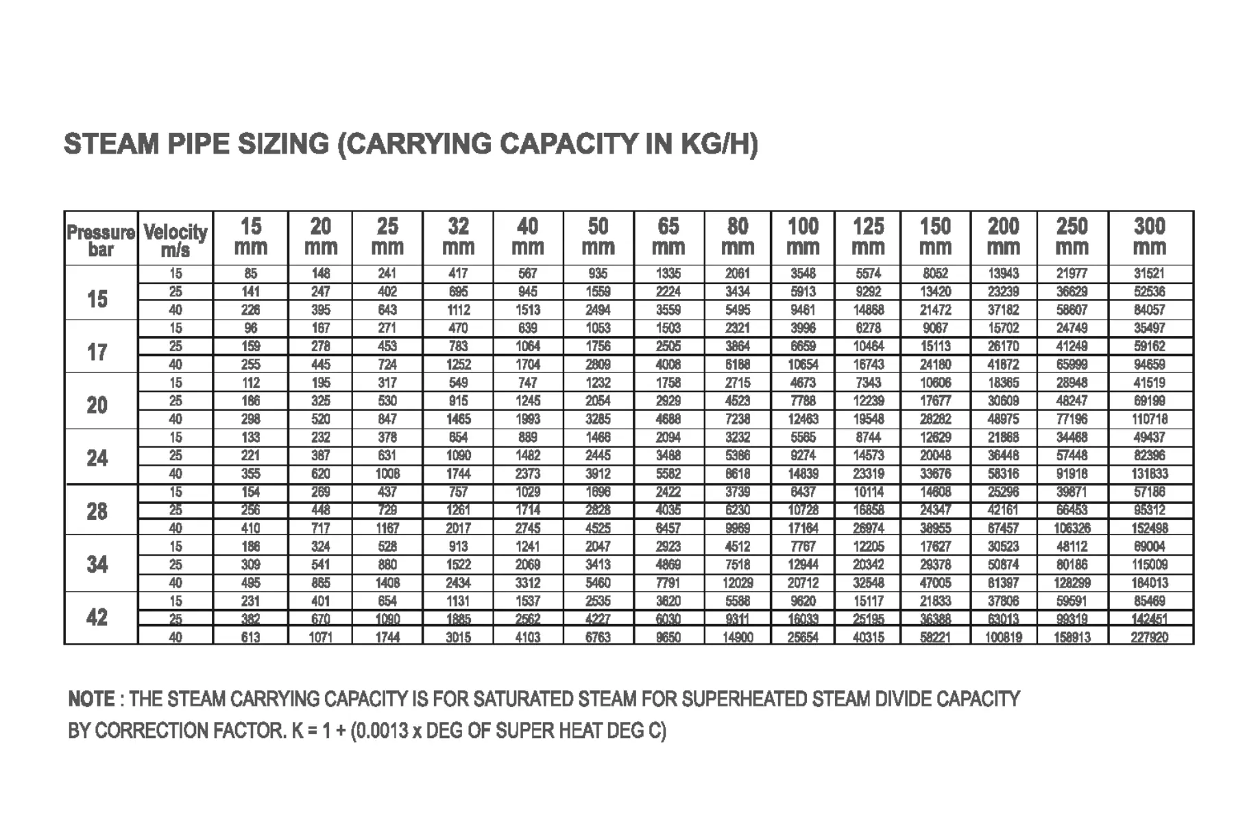
The line size for flash steam and saturated steam can also be selected using the following table. The following table tabulates results of pipe sizing based on velocity method and can be used as a ready reckoner for various applications.
Table: Steam pipeline sizing by velocity method


3.3.2 Pressure Drop Method
One drawback of the velocity method is its failure to account for the pressure drop that occurs within the steam pipelines. In actual plant scenarios, pipelines can extend for kilometers, experience changes in elevation and incorporate various accessories, all of which contribute to pressure drops. Therefore it is necessary to consider the pressure drop and verify whether the same is within an acceptable limit.
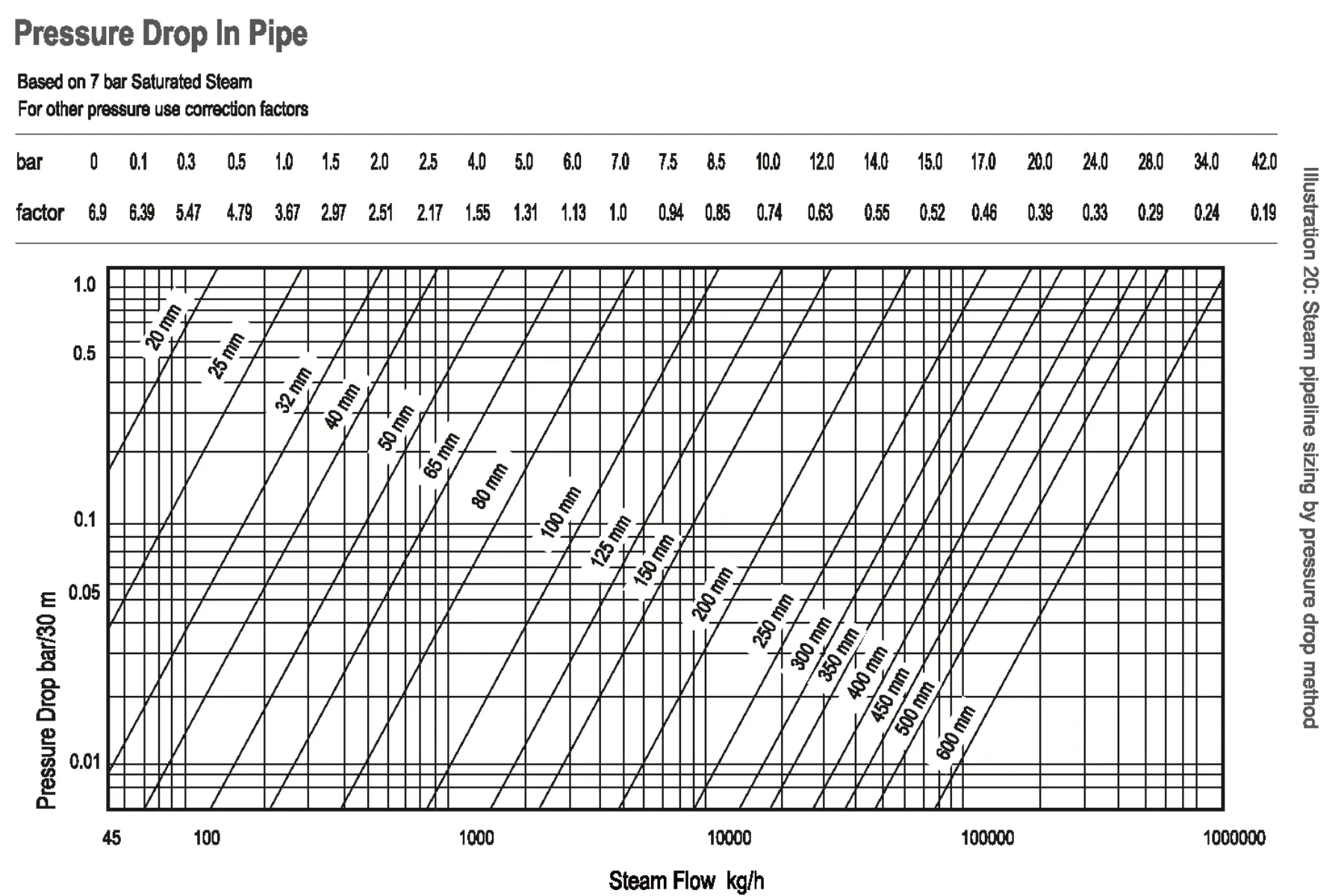
The pressure drop over a given pipe length should not exceed 10% of the steam inlet pressure or 1 Barg, whichever is less. Refer to the sizing chart, which is based on the pressure drop method.
Illustration: Steam pipeline sizing by pressure drop method

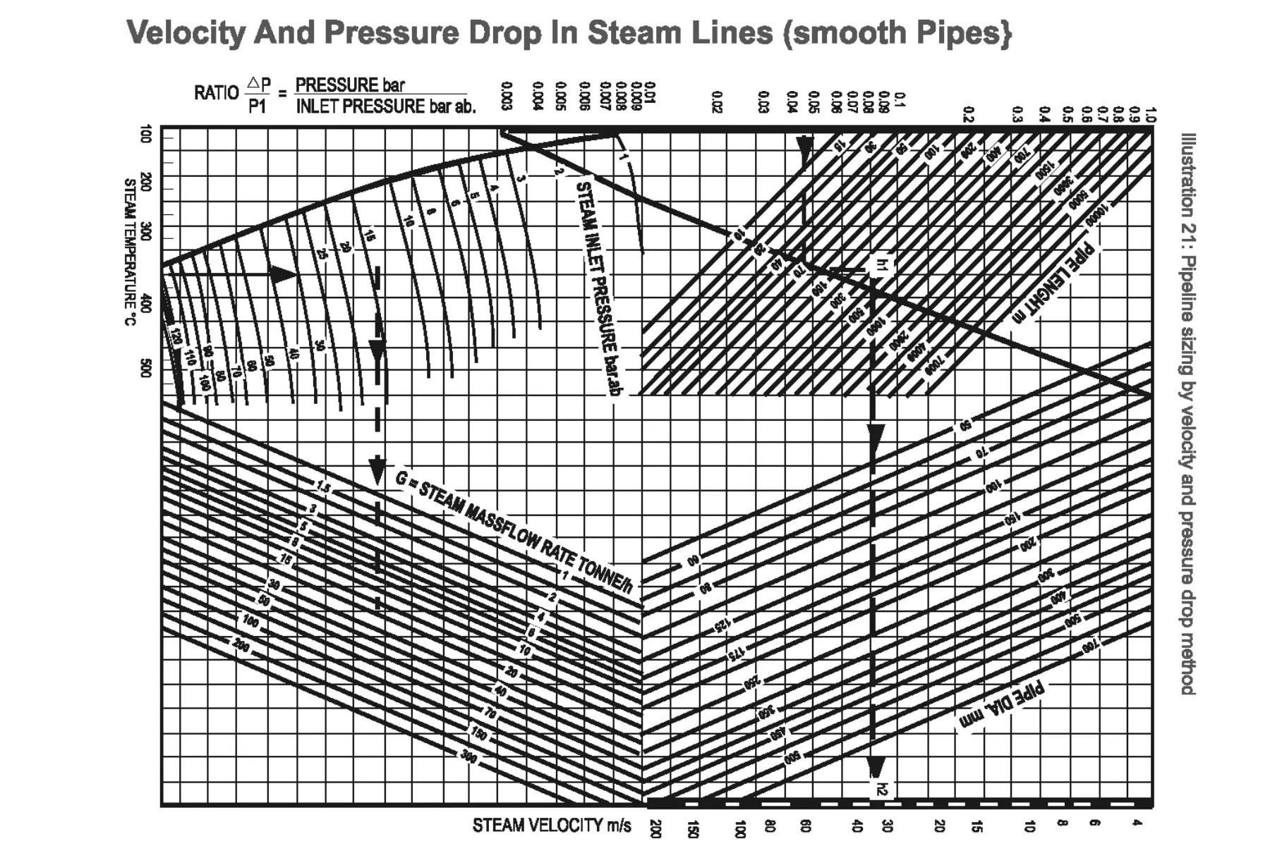
Illustration: Pipeline sizing by velocity and pressure drop method

How to use the Chart – EXAMPLE
Required to size a pipe to handle 20 tonnes of steam per hour at a pressure of 14 barg and a temperature of 340°C ..
The length of the line is 300 metres and the permissible pressure drop over this length is 0.675 bar.
Note that the chart is in absolute pressure and for an exercise of this kind it is reasonable to assume that 14 bar gauge equals 15 bar absolute.
First find the pressure drop ratio,
Ratio = Pressure drop / Inlet pressure (ab.)
= 0.675 / 15
= 0.045
From this point on the left hand scale read horizontally to the right and at the intersection with the curved line read vertically upwards to meet the length line of 300
metres. At this point extend a horizontal line h1 h2 across the chart.
Now from the base temperature line at 340C extend upwards to meet the 15 bar abs. pressure line.
Read horizontally to the right to meet the capacity line of 20 tonnes/h and from this point extend a line vertically upwards. Where this intersects the line h1 h2 indicates the pipe size required.
Where this intersection comes between two pipe sizes, the larger should be used. The procedure can of course be reversed to find the pressure drop in a known pipe
size.
As a rule of thumb short branch lines to individual process equipment with lengths <30 meters can be sized using the velocity method. For all other pipelines it is
recommended to use a combination of both velocity and pressure drop method before selecting the line size.
Example:
Consider a scenario where two plants require 3tons/hour of steam for their respective processes. In the first plant, the distance between the boiler house and the process block is 30 meters, whereas in the second plant it is 300 meters. According to the velocity method, a 100NB pipeline is adequate to handle a flow-rate of 3 tons/hour.
When the distance is 30 meters, the pressure drop in the 100NB pipeline is 0.09barg, which is acceptable. However, when the pipe length extends to 300 meters, the pressure drop increases to 0.9barg, exceeding the acceptable limit and rendering the 100NB pipeline unsuitable. Taking the pressure drop into account, the recommended line size becomes 125NB.
