Sizing of condensate recovery lines
It is crucial to design and size condensate recovery pipelines correctly to ensure efficient recovery as well as trouble free and safe operation of the system.
Condensate pipeline sizing depends upon a number of factors including condensate loads, the distance between the condensate source and the collection point, bi- phase flow (presence of condensate-flash steam mixture) and the allowable back pressure in the system.
Incorrect condensate pipeline sizing can lead to several issues.
Table: Impact of incorrectly sized condensate pipelines
Condensate Pipelines | Impact |
|---|---|
| Oversized pipelines | Higher capital cost for piping, accessories, supports and insulation. |
| Higher boiler fuel consumption as a result of a drop in condensate temperature on account of higher radiation losses. | |
| Undersized pipelines | Impact on the process, unsafe plant conditions and potential damage to equipment, pipelines and accessories due to flooding of the condensate return pipelines. |
| High back pressure in the system, reducing the discharge capacity of the steam traps, leading to condensate logging in the equipment and associated problems. |
In order to size condensate pipelines correctly, it is important to understand that these pipelines can be classified into five key stages / categories. Condensate pressure at each of these stages is different. This needs to be kept in mind during design as it necessitates separate sizing considerations (refer to the illustration and table).
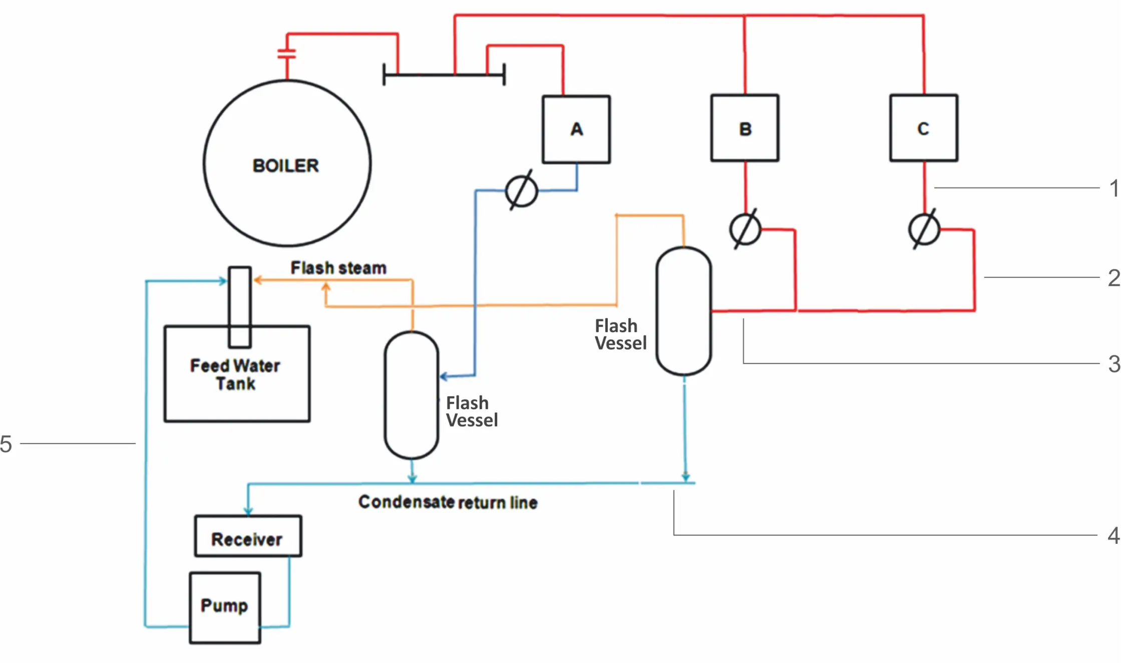
Condensate pipeline sizing
Table: Considerations for different sections of condensate lines while sizing
| Sr | Pipeline | Description | Condition of condensate in the pipelines | Sizing should be based on |
|---|---|---|---|---|
| 1 | Drain pipeline to the steam trap | Pipeline from the condensate outlet of the equipment to the inlet of the steam trap | Condensate is at the same pressure as steam supplied to the process equipment. | High pressure condensate |
| 2 | Discharge line from trap | Pipeline from the outlet of the steam trap to the inlet of a common collection pipeline | Low pressure condensate and flash steam are both present | Low pressure flash steam |
| 3 | Common return pipelines | Common collection pipelines to the inlet of the flash separation vessel | Low pressure condensate and flash steam present | Low pressure and high quantity of flash steam |
| 4 | Condensate common pipeline | From the outlet of the flash separation vessel to the inlet of the condensate recovery pump | Low pressure condensate is present | Low pressure condensate |
| 5 | Pumped return lines | Common condensate pumped return lines up to the feed water tank | Low pressure and high quantity of condensate is present | Low pressure and high quantity of condensate |
Sizing of the pipeline from the equipment outlet up to the steam trap
Condensate discharged from the equipment outlet will be at the same pressure as steam, thus flash steam will not be formed in this section of the pipeline. As the volume of condensate does not change with a change in its pressure, condensate pressure itself will not affect the sizing of the line.
As steam loads at startup are significantly higher than running loads, this segment of the pipeline should always be sized to accommodate the startup load. It is recommended to calculate the exact startup loads before determining the line size. Typically, the pipeline and steam trap will have the same size to accommodate these loads.
The line itself should have a slight slope to facilitate flow of condensate to the steam trap by gravity. It is also important to keep the pipeline length as short as possible and install the steam trap in close proximity to the equipment. This arrangement helps prevent steam locking, a condition where steam accumulates and blocks the condensate flow.
The pipeline can be sized using the following formula
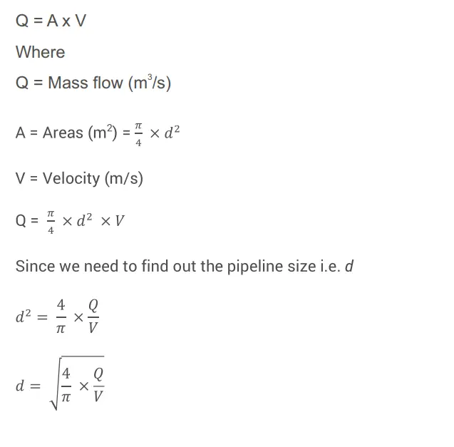
Since the quantity of condensate load is already known in kg/hr it needs to be converted into m³/s.
If the condensate load is 300kg/hr, as the density of water is approximately 1000 kg/m³, to convert 300 kg of water to cubic meters (m³), you can use the equation:

To convert cubic meters per hour (m³/h) to cubic meters per second (m3/s), you need to divide the flow rate in cubic meters per hour by 3,600 (the number of seconds in an hour)
Hence in the below equation
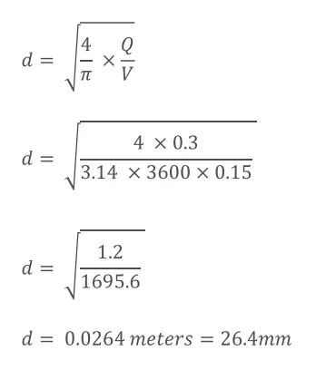
Going by the commercially available size a 25NB line can be used.
Sizing of the Discharge pipeline from the steam trap
At outlet of the steam trap low pressure condensate and low pressure flash steam are present.
Hence the pipeline needs to be sized to cater to the volume of both condensate and flash steam.
For example, if an equipment is operating at 8barg with a steam flow rate of 3,000kg/hr and the trap has a back pressure of 2barg the volume of flash steam and condensate first needs to be established and the line size selected based on the same.
The flash steam can be computed using the formula below:
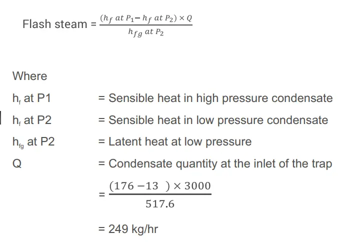
Condensate quantity at outlet = 3,000 – 249 = 2,751kg/hr
Volume of condensate at 2 barg = 0.0011 x 2751 = 3.026m³ /hour
Volume of flash steam at 2 barg = 0.606 x 249 = 150.89m³ /hour
So, total volume at the outlet of trap = 3.026 + 150.89 = 153.916m³
From the above computation it is evident that the volume of condensate vis-à-vis the volume of flash steam is negligible ie 1.9%.
Therefore the pipeline can be sized based on the flash steam volume. However the pipeline should be sized such that the steam velocity does not exceed 15 meters/second.
The velocity needs to be kept much lower than for dry saturated steam to avoid the moisture / condensate present in the line from causing water hammer and damaging the pipeline.
The above formula of Q = A x V can be used.
Where
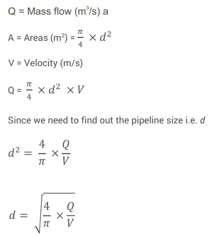
In the equation
Q should be in m3/s, we already know the value in m3/hr i.e. 150.89m³/hr. Dividing
this value by 3,600 would convert it to m3/s. Hence 150.89/3,600 = 0.0419m³/s
V =15m/s hence d can be found out
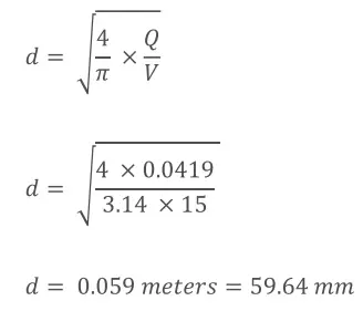
Given that the commercially available size is 65mm, a 65mm size needs to be selected.
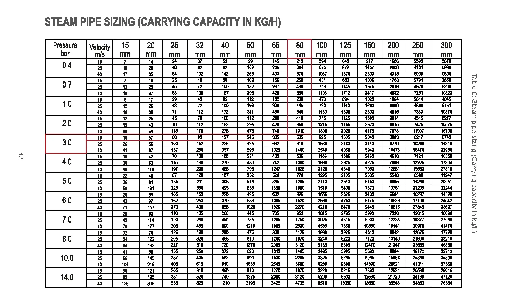
The following table can also be used to arrive at the pipeline size.
Since the flash steam quantity is 249kg/hr at 2barg in the table below look up the row corresponding to 15m/s at 3bar since in the table below the pressure is in bar absolute and 2barg = 3 bar absolute.
Since the flow rate is 249kg/hr, the flow lies between a 50mm line size and a 65mm line size. Hence the 65mm line size should be selected.
Typically if there is no lift after the discharge line and the computed line size falls between two commercially available sizes choose the lower line size. However, if there is a lift in the line, then select the higher line size.
All the trap discharge lines that are connected to a common return header should always have a disc type check valve and an isolation valve installed on the line. The check valve prevents back flow of condensate, whereas the isolation valve enables maintenance.
Sizing of the common return pipeline to the inlet of the flash separation vessel
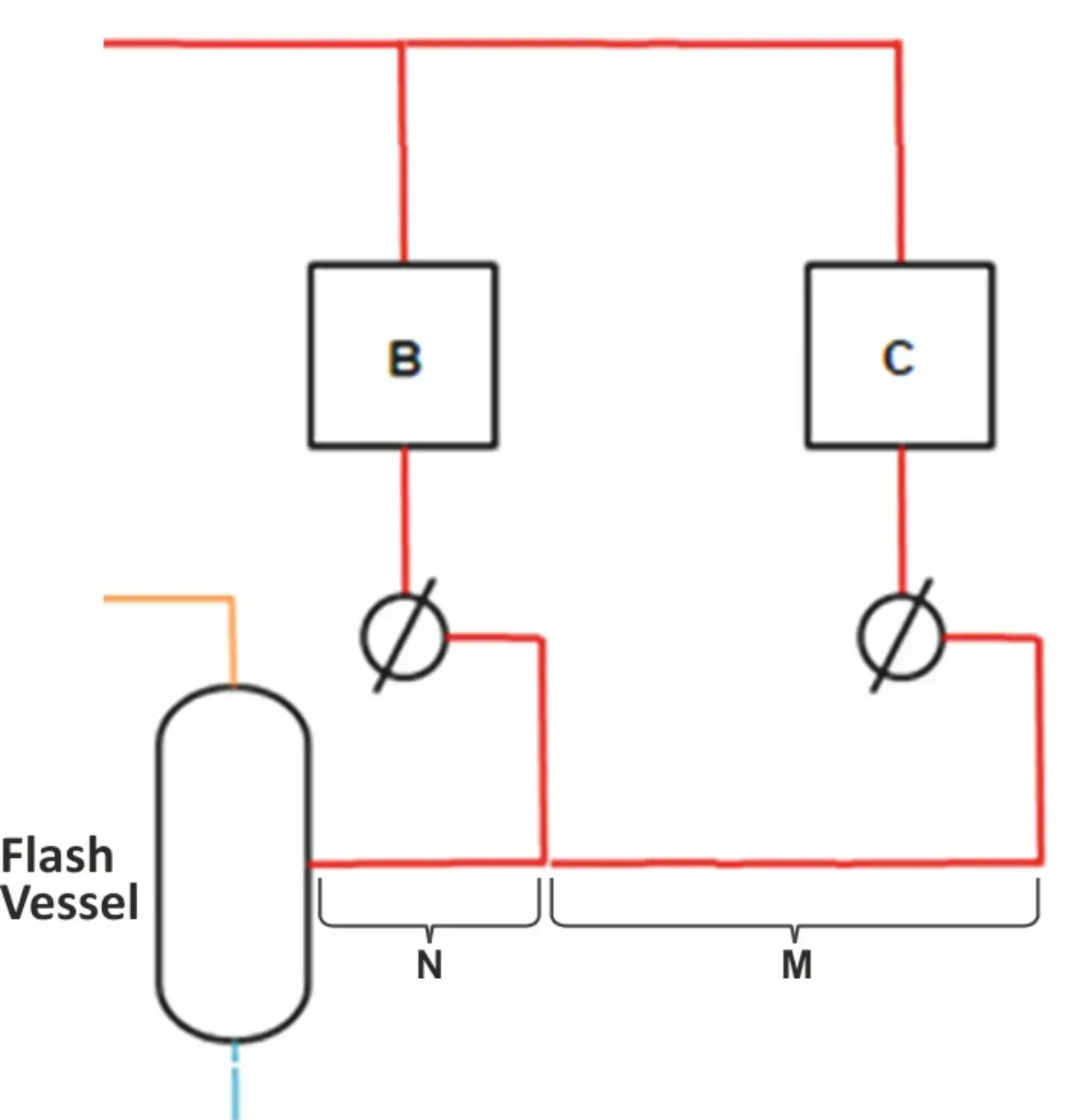
Sizing of common return lines to the inlet of the flash vessel
In practical scenarios, many traps will be connected to a common line. Each segment of this common pipeline will need to factor in the increase in discharge load from each of the additional traps connected upstream i.e. the line denoted by M will have to account for the discharge of one trap whereas N will need to account for the flow of two traps.
Common return lines are sized on the cumulative sizes of the branch lines. This is to accommodate the condensate and flash from all the trap discharges.
For example, if both B and C are operating at 8barg with a steam flow rate of 3,000kg/hr each and the traps have a back pressure of 2barg the volume of flash steam and condensate can be calculated (using the formula below).
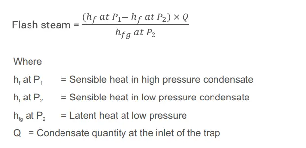
Flash steam quantity for B and C each = 249 kg/hr
Flash steam quantity for B + C = 498 kg/hr
Condensate quantity at outlet of B and C each = 3,000 – 249 = 2,751kg/hr
Condensate quantity at outlet of B + C = 5,502kg/hr
Volume of condensate at 2 barg for B + C = 0.0011 x 5502 = 6.05m³ /hour
Volume of flash steam at 2 barg for B + C = 0.606 x 498 = 301.78m ³/hour
The volume of flash steam is negligible ie 1.9%.
Therefore the pipeline can be sized based on the flash steam volume. However the pipeline should be sized such that the steam velocity does not exceed 15meters/second.
The velocity needs to be kept much lower than for dry saturated steam to avoid the moisture / condensate present in the line from causing water hammer and damaging the pipeline.
The above formula of Q = A x V can be used.
Alternatively the table below can also be used to arrive at the pipeline size.
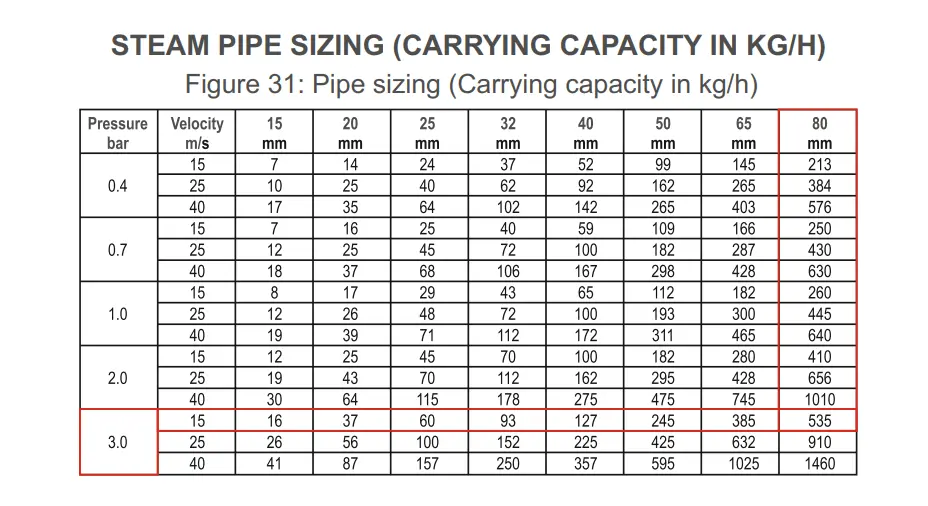
Since the flash steam quantity is 498kg/hr at 2barg in the table below look up the row corresponding to 15m/s at 3bar since in the table below the pressure is in bar absolute and 2barg = 3 bar absolute.
The flow rate of 498kg/hr, lies between a 65mm line size and an 80mm line size. Hence the 80mm line size should be selected for section N.
Similarly for subsequent sections of the pipeline up to the flash vessel, we need to continue to add the additional flash steam quantity and arrive at the line size for each section.
Sizing of the pumped return line
The pumped return line needs to be sized to cater to low pressure and high quantity of condensate.
Steam operated mechanical pumps have a cyclic operation i.e. a filling cycle and a pumping cycle. Thus the flow in the return line will be intermittent. The instantaneous flow rate in the return line will therefore differ from the condensate load and hence the instantaneous flow rate should be considered while sizing pumped condensate return lines.
Typically the pumped return line size needs to be able to accommodate three times the pump capacity i.e. its instantaneous flow rate.
The following table can be used to arrive at the pump capacity.
For example if the condensate load is 2,751kg/hr, the motive steam pressure (steam pressure available in the plant to operate the pump) is 7barg and the back pressure is 1bar, a 40NB pump is suitable. The back pressure is a sum total of the static head, frictional loss in the pipeline and the system pressure.
This selection is done by first referring to the motive pressure column in the table i.e. 7barg, followed by selecting a pump backpressure which is higher than the site backpressure of 1barg i.e. 2barg and then looking at a suitable capacity i.e. 2,830kg/hr.
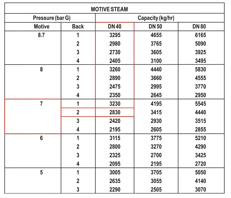
Pressure Powered Pump Packaged Unit – Pump sizing chart
Typically the instantaneous flow is three times the pump capacity and the pumped return line needs to be sized to accommodate this flow. In the example, the
instantaneous flow will be 3 x 2830kg/hr ie 8,490kg/hr. The line size can be selected by referring to the row with frictional flow of 0.8millibar/meter in the following table and then selecting the line size which can accommodate the flow of 8,490kg/hr i.e. in this case the line size is 65mm.
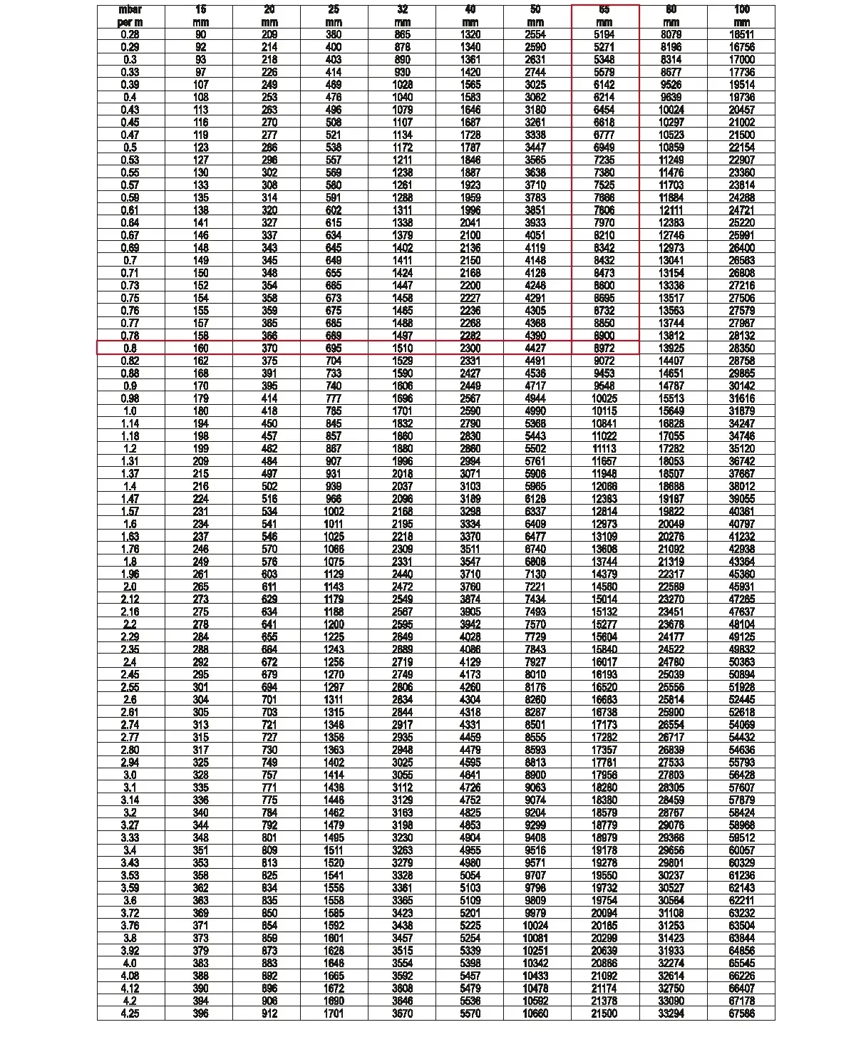
Condensate pipeline sizing
